Self-Balancing Robot
A deep dive into control systems and embedded electronicsIntroduction
Creating a self-balancing robot is a rite of passage in the world of electronics—it's the "Hello, World!" of hardware projects. My goal was to build a robot that could stand upright on two wheels, a simple concept that requires a surprisingly complex control system to manage its inherent instability.
This project was an incredible learning experience in control theory, motor drivers, and microcontrollers, culminating in a fully functioning balancing system.
The Components
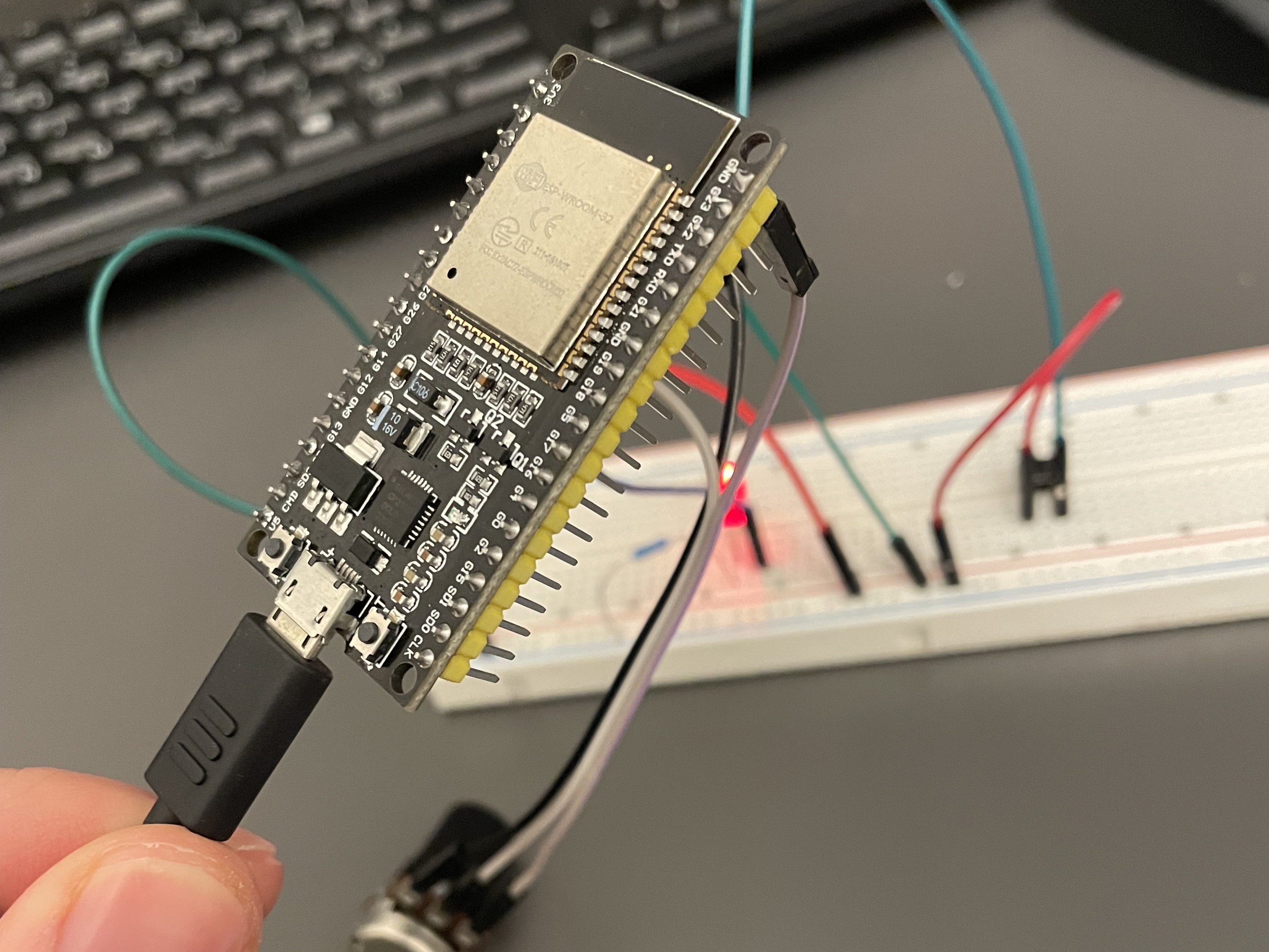
The brain of the operation is an ESP32 Dev Board, chosen for its built-in Wi-Fi and Bluetooth, which opens the door for future ROS 2 integration. I sourced most of the other components from previous kits.
- Microcontroller: ESP32 Dev Board (WROOM-32D)
- IMU: MPU-6050 Gyroscope & Accelerometer
- Motors: 2x "Yellow" DC Geared Motors
- Driver: TB6612FNG
- Power: PowerBoost 1000C & 2000 mAh Li-ion
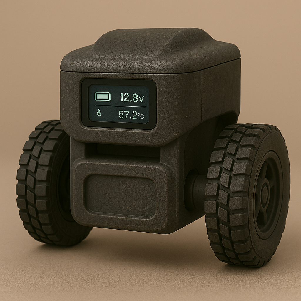
- Display: SSD1306 OLED for real-time data
- Chassis: Custom 3D printed frame
A "No-Gloss" Build Log
Electronics projects rarely work perfectly on the first try. Here are some of the key challenges I troubleshooted:
- The "Chicken-and-Egg" Trap: The PowerBoost 1000C wouldn't turn on because its enable (EN) pin was wired to its own output. The fix was tying the enable pin to the battery rail—a power source that exists at startup.
- Voltage Dips & Resets: High motor current caused the main power rail to dip, resetting the screen. A large 100µF capacitor across the motor driver's power lines solved it.
- Flux-Induced Bugs: After soldering, the low-battery indicator LED lit up even with a full battery. The culprit was a microscopic bridge of flux residue. Cleaning with isopropyl alcohol (IPA) cleared the issue.
- Motor Whine: The ESP32's default 1 kHz PWM frequency produced an audible screech. Switching to the dedicated LEDC peripheral to generate a silent 20 kHz PWM signal fixed it.
The Control System: From P to PID
The robot's ability to balance comes from a PID control loop that adjusts motor speeds in real-time. The MPU-6050 measures the robot's tilt angle (pitch), and the controller's job is to drive that angle to zero.
I started with a simple Proportional (P) controller, where motor speed is directly proportional to the tilt angle. This provided basic balancing, but it was prone to oscillations. To achieve true stability, I implemented a full PID loop:
- Integral (I): This term looks at the accumulated error over time, correcting for persistent leans that the P-term alone would ignore.
- Derivative (D): This term acts as the robot's reflexes. It measures how fast the robot is falling and applies a counteracting force to dampen the motion and prevent overshoot.
Video Demo
Next Steps on the Roadmap
With the foundational hardware tested, the next phase is to fine-tune the control loop and expand the robot's capabilities.
- Refine the Full PID Controller: The next major step is to tune the Integral (Ki) and Derivative (Kd) gains to create a critically damped system that is both responsive and stable.
- Improve Angle Estimation: I plan to implement a complementary filter or a Kalman filter to fuse data from both the gyroscope and accelerometer for a more accurate and stable angle reading.
- ROS 2 Integration: For higher-level control, I will integrate the robot with the Robot Operating System (ROS 2), allowing the ESP32 to publish sensor data and subscribe to commands.
CAD & Fabrication
The custom chassis was designed in SolidWorks and 3D printed with black PLA+.
Download STL